![]()
![]()
![]()
![]()
![]()
![]()
![]()
|
PROJECTS & PRODUCTS GALLERY Main Menu |
|||||||||||||||||||||||||||||||
|
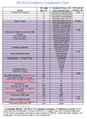
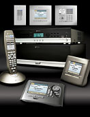
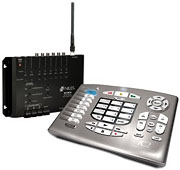
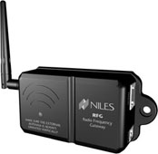
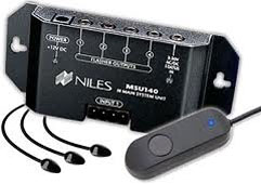
IntelliControl ICS 6-source, 6-30 zone modular Multizone System:
GXR2, RFG, RS232G, HT-MSU, iRemote + RBX-1,
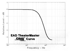
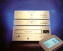
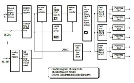
Jan 1995 TheaterMaster Classic
$6,995 (standard model);
$9,995 (Signature model). PCM63P-K
DACs (2 per ch. for L,R bal output),
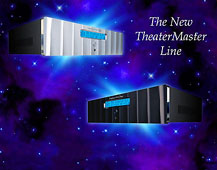
Jan 1998 TheaterMaster Encore
$3,000/Ovation
$4,500/Signature
$6,500 PCM1702 20-bit multi-bit DAC
(Signature), dual Zoran ZR83500
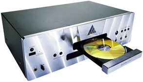
CD-1000
1993 CD player
DSP-7000
1992
20-bit DACs, 4/8x oversampling, balanced/single-ended output
options
PowerMaster 2000
$7,250 1999 (20
A option +$100) 400 W, 5-ch., 12 V
trigger, 100/120/220/240 VAC, 115 lbs
Summary:
The brew performance of my Rancilio
Silvia espresso machine was improved by using
precision temperature control (which I achieved using a custom-tuned
off-the-shelf
proportional-integral-differential (PID) industrial
temperature controller (a type of programmable logic
controller, or PLC), with platinum resistance
temperature probe, and a zero-crossing SSR).
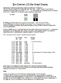
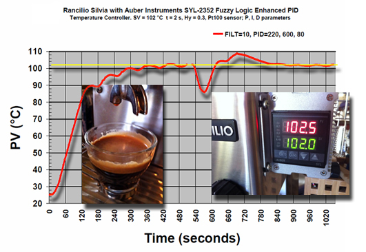
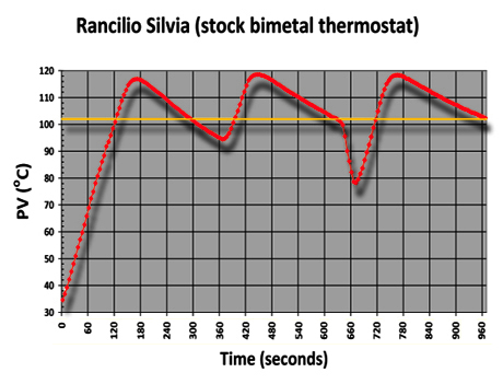
Although further tuning may eliminate the 30 second period, 2?C oscillation in parts of the process value (PV) temperature curve, this amount is not significant. It may also be possible to reduce the 8?C boiler recovery overshoot after pulling a double shot, but since I pull successive shots so rarely, it may not be worthwhile...perhaps I'll take another look at this on a future rainy day Here is the original performance of the same Rancilio Silvia espresso machine, using the stock bimetal thermostat:
Several things to notice:
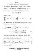
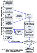
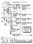
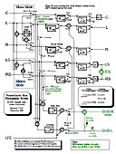
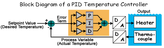
None of the available theoretical derivations for proportional/integral/differential controllers were to my liking, so I decided to create my own. The basic structure of a PID controller is shown in the following block diagram:
Given that the temperature control loop error term e at time t is equal to the difference between the desired temperature (the setpoint value or SV) and the actual measured temperature (the process variable or PV), in other words,
from the block diagram we have,
where the heating power, Output(t), is the linear weighted sum of three terms, known as PID loop tuning constants: kp = Proportional gain
(determines how strongly the current error signal affects the
output) This loop has a 2nd-order bandpass transfer function,
which has a pole at the origin, and two zeros at
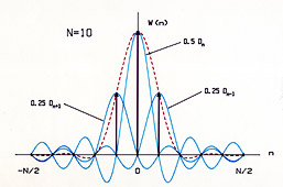
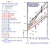
Although we could certainly implement the above differential equation directly, using various analog computer elements (built using op amps, resistors and capacitors), for various reasons such as consistency, flexibility, repeatability, and lack of drift, most modern PID controllers are implemented as discrete time (sampled data) digital systems. This is achieved by rewriting the differential equation as a linear difference equation. PID Controller Difference Equation: Assuming a uniform sampling interval, ts, (1 or 2 seconds is adequate for an espresso machine) the derivation of a difference equation for a PID controller is relatively straightforward. Good accuracy can be obtained by approximating the derivative as a 1st-order difference, and the integral using the trapezoidal rule (trapezium rule to the British). The resulting iterative equation requires storage of all past error samples. However, by transforming the equation into a recursion, we need only store two past error samples, e[n-1] and e[n-2],
which has overall data storage requirements for just three variables, Output[n-1], e[n-1], and e[n-2]. The new discrete-time constants are related to the old continuous-time constants, as follows:
Note that unlike kp, ki, and kd (which are respectively: dimensionless, 1/t, and t), the new gain constants, K1, K2, and K3, are all dimensionless. Consequently, K1, K2, and K3, do not have a simple correspondence with anything physical in the controller feedback loop. Regarded as gain constants, K1, K2, and K3 can be seen as representing the coefficients of an infinite impulse response (IIR) digital filter. Choosing suitable values for them will give a type of bandpass filter response matched to the heating and cooling time constants of the espresso machine's boiler. Many off-the-shelf PID units have an automatic tuning mode that can deal with this. So, there you have it! The mystique of PID essentially boils down to a single line of code (the equation in the yellow box, above), consisting of three multiplications and three additions, replacing all of that calculus with a discrete-time approximation that is "close enough." The controller consists of a main control loop iterating this simple line of code perhaps once per second (achieved using a periodic timer interrupt). Together with a little house-keeping for three memory locations that store the filter's state between iterations, that's all there is to a PID controller. Implementation: If the PID sampling rate (1/iteration time) is insufficient, time-domain aliasing error may be significant, and the control loop will not track rapid changes properly. Another possible source of error is data quantization. A detailed analysis shows that a digital PID temperature controller with sixteen-bit arithmetic is sufficiently accurate for espresso making (achieves an accuracy of around 1% or better). Normally the PID controller will drive a solid-state relay (SSR) that is in series with the boiler heater and power source. However, since most SSR are designed to be controlled by a simple on/off logic signal, this requires a small additional piece of code to convert the Output[n] variable produced by the linear discrete time difference equation, to a corresponding pulse-width, in other words, code that will convert the output to a proportional on/off duty cycle. Many designs also prevent a phenomenon called integrator wind-up, by including additional code to limit the magnitude of e[n]. Between iterations and before reading the next e[n], don't forget to transfer e[n-1] to e[n-2], followed by e[n] to e[n-1]. If you are an adventurous DIYer, you may like to implement this by moving a pointer on a three-level circular stack. As mentioned above, the water boiler requires a heating power that is proportional to the linear Output[n] variable, something that cannot be achieved using a typical solid-state relay (SSR), most of which are simple on-off AC power switch replacements designed to be controlled by an on-off binary logic signal. Therefore, in order to smoothly control the heater power proportional to Output[n], most PID controllers arrange for the logic signal to switch on and off with a corresponding duty cycle, with a period that is much smaller than the thermal time constant of the espresso water boiler (say 1%). A period of a second or two is usually fast enough, and most PID controllers use this approach due to its hardware simplicity and low cost. The method does have its issues, however, since cycling the full boiler heater current on and off at random times relative to the mains waveform has the potential for creating strong RF interference (RFI), and may also cause lighting devices on the same circuit to flicker up and down in brightness due to mains wiring voltage drop. We normally don't need to be too concerned about RFI since good SSRs mitigate it through built-in mains zero-crossing detection, which switches the load only when the current is small. There are many different ways to do the conversion of the (typically 8-bit) digital Output[n] signal to a duty cycle, However, I'll describe just one, as an example: The firmware turns on the SSR drive bit, and starts a timer. When the timer reaches the Output[n] value, the SSR drive bit is turned off, and the timer is reset. Another timer (or even the same timer) can be used to complete the cycle by determine the downtime between pulses sent to the SSR. In choosing the timer delays, we need to keep in mind that SSRs switch whole numbers of AC mains cycles, i.e., in multiples of 16.7 ms (20 ms) for 60 Hz (50 Hz) mains voltage. For 1% control resolution this implies output pulse widths that vary from single cycle to 100 cycles, i.e., 16.7 ms (20 ms) to 1.67 s (2.0 s). Due to the modest arithmetic and speed requirements of espresso PID, even tiny microcontrollers costing less than $2.00, such as the Microchip PIC12F617 can do the job. Therefore, given how little hardware is needed to build a digital PID controller, why pay $50 to $200 for a commercial unit? Apart from the pretty lights and readouts, a list of good reasons would undoubtedly include auto-tune and the modular convenience of an off-the-shelf solution.. Such solutions also typically include out-of-bounds checking and limiting for process variables, and have a built-in interface which relays useful process information (such as PV) to the user, which also allows easy modification of process constants. The tuning algorithms used in off-the-shelf controllers tend to be proprietary, and no attempt will be made to cover them here. Conclusions: The objective when tuning a PID temperature controller is to achieve the required temperature as quickly as possible, with minimum overshoot, and maintain a temperature that is as stable as possible, recovering quickly after the influx of cold water into the boiler while pulling a shot. The Auber PID controller I used is "fuzzy logic enhanced," which due to an unfortunate lack of information about what exactly that is, and how it interacts with the PID algorithm, makes the controller more difficult to fine-tune. I was not satisfied with the performance (i.e., the temperature vs. time curve) after using auto-tune (I ran auto-tune many times), so decided in the end to use auto-tune only as a starting point, and then manually attempt to adjust the controller for better overshoot performance. A particular quirk is a 5 ?C overshoot after pulling the first shot (the bump at 720 seconds in the first graph, above), which slows the recovery time. I suspect that its algorithmic fuzziness is not taking into account the higher starting temperature after the initial ramp up. Fortunately, I don't often pull more than a single double shot, and when I do, I can run off a quick burst of water to cool the boiler slightly. There are other PID controllers on the market without the fuzzy logic, which may be easier to adjust, but they are much more expensive than the Auber Instruments unit. The PID parameters I am currently using are: SV = 102 oC, Hy(steresis) = 0.3, t = 2 s, FILT(er) = 10, P = 220, I = 600, D = 80. However, even if the controller performance is not yet quite ideal, one consolation is that (compared to the mechanical thermostat it replaced) the temperature performance is still hugely improved, consistent with the ultimate aim of good espresso extraction: preservation of the flavor. Too cold and the extraction does not happen properly, causing flavor imbalance; too hot and some flavor components will be burned. These (relatively small) issues aside, because (apparently) the Auber's fuzziness is active only during auto-tune, and not during normal processing, its process behavior is absolutely consistent, as should be the case for any good digital PID. Moreover, the same parameters can be dialed in to an identical model Auber controller on another same model espresso machine, and without further tuning, the results will be identical. INEI Standard for an Espresso Single Shot:
|
|||||||||||||||||||||||||||||||
|
|