![]()
![]()
![]()
![]()
![]()
![]()
![]()
![]()
![]()
![]()
![]()
      |
| TECHNOLOGY INNOVATION & DESIGN Main Menu | |||||||||||||||||
|
1) Carving Out a Little Piece of Audio History...
Where:
Winter CES, Las Vegas, NV
Significance:
The
TheaterMaster
was not only the very first consumer product
in the race to market a
decoder
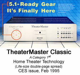
The TheaterMaster Classic
shipped to customers February 1995.
Introductory pricing for Standard model: $5,950,
Signature model $9,995.
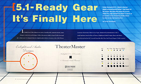
A Tale of Two CESs All who visited the EAD show room in the Sahara Hotel's Alexandria Towers, January 12-15, 1995, were enthralled by the sound of the TheaterMaster. The visitors included three Dolby sound engineers who had been involved in the AC-3 development. The high quality of TheaterMaster's playback from a pre-release copy of U2's Rattle and Hum laserdisc created an emotional moment for this VIP audience. One of them, Steve Thompson (supervisor of the AC-3 encode for the critically acclaimed remastered 5.1-channel Rattle and Hum concert soundtrack recordings), said, "I've never heard AC-3 sound so good!" In fact, as recounted in the February 1995 issue of Home Theater Technology magazine (HTT) by Technical Editor Corey Greenberg, January 1995 was the second showing of TheaterMaster at CES. The first was in Chicago at the June 1994 Summer CES, six months before. Corey wrote: "The [emphasis Corey's] High-End company, Enlightened Audio Designs, however, jumped the gun on everyone when they introduced their muy expensivo AC-3-ready TheaterMaster surround preamp/processor at CES back in June: this dazzling gem should be in the salons now..." And then with reference to actual working Dolby Surround AC-3 introduced at winter CES, in Las Vegas just weeks before, Corey wrote further that, "Dolby 5.1 is finally here, and it's really something incredible. At HTT, we've got Runco's 5.1-ready IJR II laserdisc player and the EAD TheaterMaster right now.... Hey, somebody's got to be Number One. And we like the way the hat fits." (HTT Feb 1995, p. 89) The TheaterMaster shown six months before, at the summer CES in Chicago, was a functional prototype, equipped with the same DSP hardware as the production TheaterMaster introduced in Jan 1995 at the Winter CES, but differing in details such as D/A converters, remote control, etc. At that time Dolby still had not released the home version of AC-3 to manufacturers, and so our June 1994 CES demonstration instead used an available digital Pro Logic decoding firmware for Dolby Surround encoded stereo sound tracks. "The differences are so slight, I'm not even sure I can find words to describe them!"
On Saturday,
February 14th, 1995, with an EAD
TheaterMaster in hand, Gordon Shackelford and myself, both
from EAD, became unofficial representatives for Dolby
AC-3 Surround Digital at the world's first "shootout" between
competing discrete surround sound formats. This event was
sponsored by Widescreen Review (WSR) magazine, and took place at the
home of the magazine's owners, Gary and Marlene Reber. Many
industry experts were there, including the late Brad Miller (d.
1998; live sound recordist, and founder of Mobile Fidelity Sound
Labs), the late Peter Mitchell (d. 1996; President of the Boston
Audio Society), Tom Norton (Senior Technical Editor, Stereophile
magazine), Terry Beard (founder of DTS), Ian Paisley (Chief
audio design engineer, API), Gary Reber (co-founder of
Widescreen Review magazine), Stephen Smyth (Principal engineer,
DTS Zeta Digital system), Alastair Roxburgh (Director of
Engineering, chief architect of EAD TheaterMaster, and
co-founder of EAD), Les Edelberg (President, Filter Concepts),
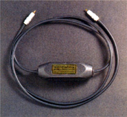
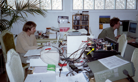
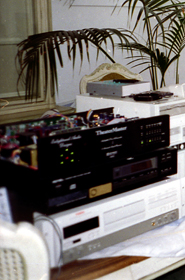
and Gordon Shackelford (Director of Operations, EAD). I remember mentioning to AlgoRythmic Technology's Stephen Smyth, principal engineer for the DTS Zeta Digital system, that based on the results of the WSR-sponsored listening tests, and to compete effectively against Dolby AC-3, DTS needed to do whatever it would take to port DTS Zeta onto a low cost fixed point DSP, even if this required a slight lowering of the audio performance. Six months later, this is indeed what happened, and TheaterMaster went on to also become one of the first, if not the first, home surround sound processors to incorporate DTS decoding, using a Motorola 24-bit fixed-point DSP. The original TheaterMaster model, with the front panel LEDs and push buttons, shown in the photographs below, is now known as the TheaterMaster Classic. Thirty TheaterMaster Classics were sold to the film industry, who used it both for QC in the manufacture of laserdisc AC-3 soundtracks, and in the 5.1-channel soundtrack mastering process. This was made possible by an addition to the TheaterMaster firmware that enabled decoding of professional formats for S-PDIF/AES. A companion EAD-designed AC-3 RF demodulator (the SmartCable) was also available. Scoring a triple win as the first consumer Dolby Digital decoder, the first high-end decoder, and the first commercial decoder that could also handle the professional data formats used in laserdisc production, the TheaterMaster quickly gained a solid reputation for sound quality, accuracy, and flexibility. It remained in wide use until, lacking THX processing (which I've always been adamantly opposed to because its Re-EQ is not compatible with 5.1 and its decorrelation is not compatible with music), the studios were put under extreme pressure to stop using TheaterMaster. The pressure, which some have said bordered on duress, came from a certain party who toured the professional facilities that were using TheaterMaster. As told to me by an insider at one of the studios, this "tourist" purported to show that TheaterMaster did not hold its calibration, and then (in a very Steve Jobsian manner) added that if use of TheaterMaster did not cease, then no more Tom Holman experiment projects would come to that studio. It seems likely that this same dog and pony show was repeated at various studios. By this time, TheaterMaster was earning a well-deserved reputation for home theater sound quality, reproducing feature film and music video soundtracks with a near-field immediacy and point-source holosonic accuracy that cannot be achieved in cinema spaces, and was frequently used as the standard against which all new-comers were judged. Widescreen Review magazine was foremost in listing the TheaterMaster Classic as part of its Reference Home Theater setup for several years.
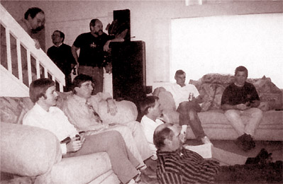
June 1994:
EAD's summer CES demonstration of AC-3-ready TheaterMaster functional
prototype, running digital Pro Logic.
Video
magazine, in its 1995 CES recap. issue (April 1995,
vol. XVIV #1): Video
magazine, September 1995:
The AC-3
demonstrations at the 1995 Winter CES had an
immediate effect...
ADA Olympus III $29,000 (sic)
Meridian 565 $3,600
McIntosh MX130
$3,600
Proceed PAV $4,195
Angstrom HED
$3,500
Citation Model 7.0
$3,700
Fosgate-Audionics Model Four $1,000
Kenwood KC-X1
$300
Lexicon CP-3 Plus
$3,200
Fosgate-Audionics Model Three A
$3,000
B&K AVP2000R $1,000
Kinergetics KSP-2
$4,500
Parasound P/SP-1000
$850
Soundstream C-2 THX
$2,995
ADA SSD-66THX (not pictured)
$3,000
Proton SD-1000
(not
pictured) $1,000
AudioSource SS-Four
(not pictured)
$300
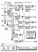
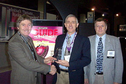
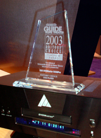
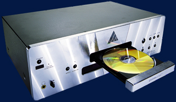
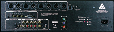
Alpha Digital won the coveted Stereophile Guide to Home Theater (now Home Theater) 2003 Editors' Choice Award: Platinum Award DVD Player, for the EAD DVDMaster 8000Pro, the first DVD-Audio player with full 5.1-channel bass management. Capable of true audiophile quality performance with 24/192 stereo, and multi-channel 5.1 or 6.0 24/96 recordings, the player was also equipped with Silicon Image 480p video processing with RGBHV (VGA) or Y Pr Pb component video outputs. All player functions including the integrated "MultiBass" bass management circuitry, and the high-quality analog volume control, can be easily controlled using the provided IR remote control, or RS-232 commands. It may be connected directly to a multi-channel power amplifier (sans preamplifier) for "minimalist" listening. All incoming IR is sensed by the original Panasonic IR receiver, but from there is rerouted to the EAD add-in board. There it is decoded and merged with any incoming RS232 commands. Those commands corresponding to the DVD-Audio players original IR command set go to an IR re-encoder on the EAD board, and from there are output just downstream from the original Panasonic IR sensing circuit, for final decoding by the player. EAD commands (such as volume up/down and surround mode, or requests for status to be output on the RS232) are processed immediately, with no retransmission. The Panasonic remote control conveniently had extra keys for volume up/down, etc., with the only (minor) hurdle being the use of a different type of IR code format for these additional functions. The EAD add-in board determined on-the-fly which IR code set it was receiving by examining the respective frame headers. The additional delay due to the additional layer of IR decode and re-encode was not noticeable. MultiBass bass management operating modes:
Level trims are provided for all bass-management modes, but channel-delay
adjustments are available only for Dolby Digital.
United
States Patent Application Publication
US 2010/0258729 A1,
filed April 13, 2009, published Oct 14, 2010.
PATENT ABSTRACT:
SUMMARY: The significance of this new IR repeater methodology is that it is one of the first to work reliably with the new high-density IR codes. Conventional IR repeaters are are designed for 30 or 40 modulation cycles per code pulse, whereas the new codes use only six cycles per code pulse. Such a short pulse is at the mercy of amplifier overshoot, ringing, and attendant recovery time, whereas a long pulse is not. The eureka moment was my realization that by using a reduced the number of capacitors in the signal path, there is a lower "Q" and consequently less overshoot, ringing, and waveform amplitude and phase distortion, all of which need to be minimized to accurately repeat the new high-density IR codes. Examples of the new codes are RC-MM and XMP, which respectively use 4-ary and 8-ary symbol coding, rather than the conventional binary (2-ary) format. The corresponding code symbols are respectively 2 and 3 bits long, rather than the 1 bit used in conventional 2-ary or binary signaling. However, due to the much lower number of carrier cycles per pulse, and the method of encoding the extra symbol bits is in the precise timing of these pulses (four different timings per symbol for 4-ary, and eight for 8-ary), signal fidelity becomes much more important to avoid intersymbol interference. Compared to conventional binary signaling, the timing precision needs to be maintained 4x better for RC-MM, and 8x better for XMP. It is difficult to maintain this degree of accuracy in high-gain amplifier circuits that have too much low frequency roll-off in the wrong places in the sensor circuit, even while maintaining a high frequency roll-off that is adequate for the highest modulation frequencies, but which may roll off too steeply. A low-Q circuit helps in these respects. Some degree of low frequency roll-off is desirable to help eliminate the 120 Hz power line modulation of incandescent lighting, but this is best added after the DC-coupled high-gain input stage. The amplifier 'Q' is also minimized by using high-gain amplifiers with a higher-than-usual gain bandwidth product. The problem with conventional IR repeaters occurs as follows: When attempting to repeat a high-density IR code there is a troublesome artifact caused by baseline shift which occurs when the in-directional IR signal charges all of the sensor's AC coupling capacitors. This pulse, which is affectionately known as a "pigtail pulse," occurs typically within a frame time of the trailing edge of the high-density IR frame, adding an extra pulse to the repeated IR frame, causing a bad decode. It is typically more prevalent at short range, when the signal is stronger, than at greater distances. The pigtail pulse does not affect conventional IR codes because the code pulses are encoded in a modulation envelope that is 8- to 10-times longer. As a result, the pigtail occurs often within the initial start pulse envelope, and is effectively masked, and does not result in a bad decode. The new design solves the problem by reducing the amplitude of baseline shift-induced overshoot and ringing in the amplifier stages so that the amplified raw IR signal remains below the data slicer threshold, thereby preventing the unwanted "pigtail" output pulse. A number of complementary techniques further enhance the behavior or the circuit. The DC servo, for example, that allows the high-gain input stage to be DC coupled, also serves to reduce or eliminate the effects of indirect and direct sunlight on the sensor. A very specialized tailored-response automatic gain control loop, which goes by the name of Universal Noise Suppressor circuit, also improves the performance of the IR sensor. A new Niles IR sensor based on this technology, the MS220, was named a Finalist for the 2010 CEA Mark of Excellence Award, Installation Product of the Year, cited as the first sensor in the industry to utilize high fidelity wideband amplification to ensure compatibility with virtually all current and emerging IR code formats, including the new Philips RC-MM code structure.
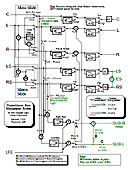
A unique feature of the 2nd-generation (Encore/Ovation/Signature or EOS) TheaterMaster is the use of a small electret microphone placed at the principal listening position, to automate the setup of speaker levels (gain) and distance (time alignment), together with automated measurement of polarity (absolute phase). For the levels measurement, the microphone captures band-limited pink noise and by using a simple servo mechanism adjusts it to the regulation set point of 80 dB SPL. For the distance measurement, the microphone captures the time-of-arrival of "sonar" pulses, from which it adjusts buffer pointer offsets to arrange for coincident time-of-arrival of sound from the main channels. The microcontroller triggers the DSP to output a sine2 pulse on all channels (directed to a particular speaker by manipulating the volume controls), and starts a hardware timer. The microcontroller then polls the microphone ADC, looking for the peak of the pulse. Assuming that the speaker under test has correct polarity, when the peak is detected, as indicated by the next ADC sample being smaller than the previous one, the timer is stopped, and its value read. Suitably scaled, this value gives the time in ms, and the distance in m. Distance accuracy is typically two ADC sample times. Sampling at 7.8 kS/s, which gives a time accuracy of 0.256 ms. Assuming 344 m/s for the speed of sound, this translates to 0.1 m, or 3.5 inches. Distances greater than 20 m are flagged as 20 m. Speaker polarity checking, which informs the user of any speakers that are out of phase with the others, or any that have inverted polarity, is a straightforward extension of the distance measurement procedure. Best reliability for the delay and polarity measurements is achieved if the sonar pulses are spectrally-tailored to avoid driving the tweeter transducer and associated cross-over filter, and focus on the midrange. A suitable choice of waveform is a sine2 pulse (for example, consisting of 50 samples output at 48 kS/s, which gives a frequency response that decreases monotonically to its first zero at 0.96 kHz). This smooth waveform is more consistently reproduced by most speakers than (theoretically superior) alternatives such as a truncated or tapered sinc function. At any rate, the main lobe of the sine2 pulse's frequency spectrum is sufficiently flat for the purpose at hand, and rolls-off fast enough to avoid significant drive to the tweeter, as shown in the following figure:
The polarity measurement idea came about one day while I was working on improving the speaker distance algorithm when I noticed that the measured time-of-arrival was wrong if the speaker wiring was polarity reversed. My 'aha!' moment occurred when I realized I only needed to invert the sonar pulse to get the correct distance on an incorrectly phased speaker. Investigating, we found that by using an appropriate threshold, say S, to reject a more minor opposite polarity, speaker-dependent, precursor in the microphone signal, we could get a sensible, repeatable distance from a speaker that has correct polarity but not so straightforwardly from a speaker that is reversed (an inverted polarity speaker inverts the polarity of the precursor, and were it not for the threshold detector, the precursor pulse could get accepted and yield a consistent distance).
If both polarities still succeed (e.g., if the precursor is much more pronounced in a particular speaker model, exceeding S), it is clear that the correct distance is the latter one. Hence, by keying the DSP chip to transmit several normal-polarity sine2 pulses, about 1 second apart, until a consistent delay is measured (or not), and then about 1 s later several inverted pulses similarly, we can infer the speaker polarity from whether a sensible, repeatable distance was obtained from the first (positive) group of pulses or the second (inverted) group. If both are sensible and consistent, we take the larger of the two delay measurements because that will generally be due to the principal sine2 response, which always follows the precursor response. The speaker is flagged as having inverted polarity if the larger delay measurement is from the inverted sine2 pulses. After the distance/polarity measurement procedure, the EOS TheaterMaster displays a pictorial representation of the speaker array, in which correct polarity is flagged with a "+" and inverted speakers with a "-". The user needs only to invert the wiring to any "-" speakers and repeat the test as a double-check.
Speaker polarity relates to absolute phase, where audiophiles (and the Dolby specifications) specify that a positive impulse signal on a recording should increase sound pressure when it is acoustically reproduced. All speakers in a multi-channel surround-sound system must be connected in phase for pair-wise stereo sound-field reproduction. However, the ideal of a positive absolute phase should also be adhered to for the greatest audio realism.
A problem for THX dipole speakers is that there is no direct sound, which means that the first sound heard by the setup microphone has arrived later due to reflection from a room boundary (or not arrived at all, as in an op
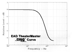
CinEQ cinema equalization curve based on Jim Fosgate's HF shelf filter. Realized as a 2o-order IIR digital filter, the CinEQ filter deviates less than 1 dB from the measured amplitude response of the higher-order THX ReEQ filter. Unlike THX's Re-EQ filter, this filter does not care about phase. Also, unlike THX's Re-EQ filter, CinEQ was applied to all full-range channels, a requirement for full multi-channel "holosonic" reproduction. (Holosonic is a word coined by Gary Reber of Widescreen Review magazine, in analogy to optical holography). Considering that THX's ReEQ filter was developed in the context of matrixed Dolby Surround, in which the surround channel is already rolled off, and that most 5.1-channel material is full-range in all five channels, ReEQ is generally inappropriate for 5.1 music, especially if recorded from the musician's perspective (music all around you), and is far less than optimum for 5.1-channel movies soundtracks. It is a minor mystery why the THX company did not extend ReEQ to all five main channels for 5.1-channel material.
Under construction.
Under construction.
My display experiments suggested how to automate loading of custom character bit maps into the Hitachi custom graphics random access memory (CGRAM), overwriting the custom character identifier (e.g., 'T' for capital T) and font attribute (e.g., 'B' for chalkboard style bold ) using a 3-bit (0-7) pointer to the appropriate part of the CGRAM bit map: As an example, consider that the LCD screen is displaying the following string at position 0 on the LCD screen: '^^^TheaterMaster^^^^'. This consists of 13 bold custom characters, and 7 spaces denoted by '^'. Out of the 13 custom characters, exactly eight are unique, consisting of TB, hB, eB, aB, tB, rB, MB, sB, where the 'B' attribute denotes the bold font.
These custom
characters are stored in the host processor and the LCD CGRAM,
as follows: Let's imagine that we then want to overwrite "Master" with bold "EQ^^^^", i.e. at screen position 10.
Step 1: Detect all
occurrences of custom characters in the section of the screen to
be overwritten, and decrement relevant entries in the 8-element
occurrences table. This leaves the above two 8-element arrays as
follows (the changes are high-lighted in red):
dc.b 'E'
At the end of this
process, the CC_table arrays look like this (changes
high-lighted in red): Thus, you can see how the CC_table_num array and decrementing mechanism, in effect, maintains a list of "free" CGRAM characters; whenever a section of the display is to be overwritten, any custom characters found there causes the relevant element of this table to be decremented. Any zero element represents a free CGRAM code, and whenever that code is used for a new custom character, that zero element is incremented for each use of that custom character. Remarkably, the most dynamic and complex-seeming display, the 6-channel VU meter, requires exactly all eight custom characters, re-used for each audio channel. Since the VU meter uses 16 different custom characters, although for six channels, only six at a time (and in the next generation of TheaterMaster, 8 channels, 8 at a time), the CGRAM and CC_table update process occurs frequently, on average about (6/16)*10 Hz = 3.75 Hz for six channels, and (8/16)*10 Hz = 5 Hz for 8 channels, given a typical 10 Hz update rate for the VU meter. Due to the high efficiency of the program code, the 2 MHz 68HC11 host processor can keep up with these rates with no apparent impact on other housekeeping functions. With LCD character coding experiments completed, I wrote up a specification. I shared it with Sunil Rawal, who had volunteered to write the final driver code (and did so over one weekend). Sunil's speed can be attributed as much to his skill as a programmer as to my insistence that he use stack frames for all local variable storage (a technique assisted by some of the 68HC11's 91 new instructions that go beyond the original M6800, namely: pshy, xgdx, subd, addd, cpd, and puly, that extend the M6800's pshx, txs, tsx, and pulx). The stack frame makes coding much easier and is particularly valuable for processors having only a handful of registers because it effectively multiplies the number of registers many times over, and furthermore allows each defined location in a stack frame to be named after the 8-bit or 16-bit variable that it holds, and which appears in the code as an index offset into the stack frame (e.g., cpd CC_id,x points to the third word in the SCREENS local variable stack frame, see below), helping eliminate coding errors. Stack frames for local variable storage are particularly efficient in the EOS TheaterMaster because the instruction set of its 68HC11 microprocessor was expressly designed to facilitate this approach. The only downside to this method of programming is that while it is much easier to write straightforward, bug-free code using this method (which allows the programmer to deal with meaningful variable names rather than cryptic register names, such as A, D, D, X, Y), the fact that variables are dynamic, rather than static, makes debugging more challenging. The following code fragment, which has six local variables accessed this way (highlighted in red), will help make it clear how this works:
;********* LCD
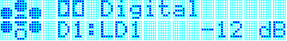
Driver ********* Formatted strings to be written to the LCD using this driver use the following general format: the plain ASCII character codes are optionally augmented by a "font" code. For example, to write Dolby Corporation's trademark "Double Dee" followed by "Digital" with an improved lowercase "g" requires three custom characters, two for the Dolby "Dee" and one to give "g" a true descender:
DD_blurb:
dc.b ')(^Digital|' where '^' indicates a space and is used here purely for clarity. Spaces on the second line indicate the standard character set resident in the LCD?s CGROM, and the other characters indicate which custom character sets will be used. In this example, ?S? indicates Symbol font, and ?L? indicates an improved lowercase descender font. The display string must end with a '|' marker. The driver controls the starting position, which we chose to be 4 in this example. Control of the starting position allows the convenient definition of short strings that often must be written to a particular place on the screen (see a second example below) or constructed on the fly, as in the case of the multi-channel VU meter. Note that the ?)? and ?(? display characters in the Symbol font denote the two halves of the Dolby double-D symbol, Ldee and Rdee (see custom font data example below). This would be rendered on the screen as follows:
This screen template would typically be over-written with an array of six characters that represented the audio channel configuration (a "daisy" shape that uses four unique custom characters, showing 5.1 channels in this example), together with other information which would normally be displayed, such as the source selection and the volume level. The following string definition and call to the display driver subroutine shows how the Dolby Digital screen shown above may be modified on the fly. Behind the scenes, the display string is loaded into a display buffer; the three custom characters are loaded into unused locations in the LCD display's CGRAM; the custom character ASCII codes in the display buffer are overwritten with CGRAM address values in the range 0 to 7; and finally the display buffer is written to the DRAM in the LCD display device. In this simple example we assume that the display was initially cleared, so that there is no need to determine which of the eight custom characters must be preserved because they are still in use). The code for the other screen items is similar.
daisies: The final screen is shown below. The total number of unique custom characters is seven, leaving one unused:
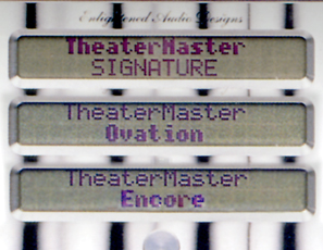
The limit of eight
custom characters was short of the initial design requirements
in several cases of the TheaterMaster screens. For instance,
while "Encore" (6 unique chars) and "Ovation" (7 unique chars)
can be rendered in an attractive "chalkboard" bold (uses a
double vertical column of pixels on the LHS), "Signature"
cannot, since it has 9 unique chars. On the other hand,
"TheaterMaster", which is much longer, can be rendered in bold
using all eight (TheatrMs). Nevertheless, regarding the
photograph of the TheaterMaster power-up screens shown above,
you may agree that this limitation did make the Signature
TheaterMaster stand apart from the lower Ovation and Encore
models. Another example of this limit of eight custom characters
affecting the design process is the CinEQ flag, which would have
required one customized character. However, because there were
cases when all eight custom characters were already in use, it
was rendered as "EQ" using standard ASCII characters. Another
trick I employed to extend the custom character limit was using
standard lowercase (cosuvwxz) to fill out a custom small-caps
font. The custom character storage format was as follows:
Note: Some VFD
displays (e.g., Noritake), unlike the majority of LCD displays,
do not allow custom chars to use the last pixel row, which
requires modification of some characters, for example, descender
characters squashed by one pixel row (to avoid going above row
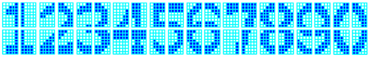
three or below row seven). The Big_Nums fonts were used for a large-sized dB volume pop-up, easily readable at a distance. To make it easy to construct Big_Nums display screens, ten different fonts are used, one per numeral, each containing four custom character bitmaps, written as 'A' (upper LH), 'B' (upper RH), 'C' (lower LH) and 'D' (lower RH). Due to the limit of eight custom characters on screen at a time, the volume readout was limited to two big digits (requiring all eight CGRAM bit maps), plus a normal sized digit for the decimal fraction, the minus sign, the decimal point, and the "dB", e.g., -23.2 dB.
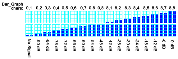
The Bar_Graph character set (see below), at 6 dB per step, together with the help of a DSP peak-detector routine, shows the peak value of channel signals from 0 dB (full scale) to -90 dB. Two small details: The gap between the LCD character rows counts as 6 dB, and the bars are split down the center so that they may be paired without any visual impairment due to the inter-character gaps. Only eight custom characters are required to show activity on multiple channels, e.g., LS, LF, C, RF, RS, and SW, or LF, and RF.
Under construction.
I was the developer of a pattern-matching heuristics-based ?Spectral Edge Frequency? EEG analysis strip chart output for the BMC, a pioneering Intel 8080A-based embedded clinical EEG analysis computer, useful in the detection of ischemic events during carotid endarterectomy. Under construction.
Under construction.
|
|||||||||||||||||


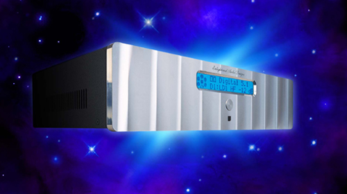
 The
EAD Encore/Ovation/Signature (EOS) TheaterMasters use a graphics
driver intended to wring as much performance as possible out of 2-line x 20-character LCD displays that use a Hitachi
HD44780 or compatible driver chips (the HD44780 supports various display sizes up to 20
chars x 4 rows in an 80-Byte DDRAM, 240 fixed chars in a 9290-bit
CGROM, 8 custom chars in a 64-Byte CGRAM, and R/S, R/W, E clock, 8
data). Despite the
limited resource of only 8 custom characters, due to careful
design of the GUI screens, the EOS
TheaterMasters are able to display a remarkable variety of
screens, including many eye-catching graphical elements,
multi-channel graphical VU meters, and big-sized graphical volume numbers, as the
photographs and diagrams in this section of the website attest
(also see the next section on GUI design).
The
EAD Encore/Ovation/Signature (EOS) TheaterMasters use a graphics
driver intended to wring as much performance as possible out of 2-line x 20-character LCD displays that use a Hitachi
HD44780 or compatible driver chips (the HD44780 supports various display sizes up to 20
chars x 4 rows in an 80-Byte DDRAM, 240 fixed chars in a 9290-bit
CGROM, 8 custom chars in a 64-Byte CGRAM, and R/S, R/W, E clock, 8
data). Despite the
limited resource of only 8 custom characters, due to careful
design of the GUI screens, the EOS
TheaterMasters are able to display a remarkable variety of
screens, including many eye-catching graphical elements,
multi-channel graphical VU meters, and big-sized graphical volume numbers, as the
photographs and diagrams in this section of the website attest
(also see the next section on GUI design).